In the previous step (structure final message), the data and error correction codewords were interleaved, and the final string of bits was obtained. The next step is to put them in the QR code matrix along with the required function patterns. A function pattern is a non-data element of the QR code that is required by the QR code specification, such as the three finder patterns in the corners of the QR code matrix. This page explains when and how to place the function patterns and data bits.
Terminology: Pixel vs. Module
On this page, I refer to the black and white squares of the QR code as modules rather than pixels. This is to differentiate between on-screen pixels and the black and white squares of the QR code. For example, a version 1 QR code is always 21 modules by 21 modules, even if it takes up 42 by 42 pixels on a computer screen, or 105x105, and so on.
Overview of Function Patterns
QR codes must include function patterns. These are shapes that must be placed in specific areas of the QR code to ensure that QR code scanners can correctly identify and orient the code for decoding. The following image gives an example of what the function patterns are and where they are positioned.

The finder patterns are the three blocks in the corners of the QR code at the top left, top right, and bottom left.
The separators are areas of whitespace beside the finder patterns.
The alignment patterns are similar to finder patterns, but smaller, and are placed throughout the code. They are used in versions 2 and larger, and their positions depend on the QR code version.
The timing patterns are dotted lines that connect the finder patterns.
The dark module is a single black module that is always placed beside the bottom left finder pattern.
The sections below explain in greater detail how to position the function patterns.
Step 1: Add the Finder Patterns
First, put the finder patterns into the matrix. The finder pattern (shown below) consists of an outer black square that is 7 modules by 7 modules, an inner white square that is 5 modules by 5 modules, and a solid black square in the center that is 3 modules by 3 modules.

The finder pattern is designed to be a pattern that is unlikely to appear within the other sections of the QR code. The module widths of the finder pattern have a ratio of 1:1:3:1:1. QR code scanners can search for this ratio of light to dark modules to detect the finder patterns and correctly orient the QR code for decoding.
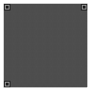
The finder patterns are always placed in the top left, top right, and bottom left corners of the QR code, no matter which version is in use.
To illustrate this, the following pictures show the locations of the finder patterns. The first image is a version 1 code, and second image is a version 18 code.

The size of a QR code can be calculated with the formula (((V-1)*4)+21), where
V is the QR code version. For example, version 32 is (((32-1)*4)+21) or 145 modules
by 145 modules.
Therefore,
the positions of the finder patterns can be generalized as follows:
- The top-left finder pattern's top left corner is always placed at (0,0).
- The top-right finder pattern's top LEFT corner is always placed at ([(((V-1)*4)+21) - 7], 0)
- The bottom-left finder pattern's top LEFT corner is always placed at (0,[(((V-1)*4)+21) - 7])
Step 2: Add the Separators
The separators are lines of white modules, one module wide, that are placed beside the finder patterns to separate them from the rest of the QR code. The separators are only placed beside the edges of the finder patterns that touch the inside of the QR code. For example:


Step 3: Add the Alignment Patterns
QR codes that are version 2 and larger are required to have alignment patterns. An alignment pattern, shown below, consists of a 5 module by 5 module black square, an inner 3 module by 3 module white square, and a single black module in the center.

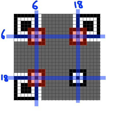
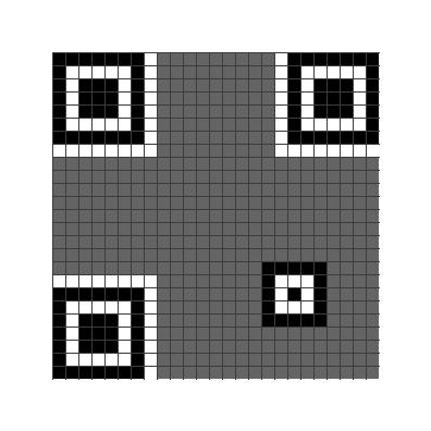
The locations at which the alignment patterns must be placed are defined in the alignment pattern locations table. The numbers are to be used as BOTH row and column coordinates. For example, Version 2 has the numbers 6 and 18. This means that the CENTER MODULES of the alignment patterns are to be placed at (6, 6), (6, 18), (18, 6) and (18, 18).
HOWEVER, the alignment patterns must be put into the matrix AFTER the finder patterns and separators have been placed, and the alignment patterns MUST NOT overlap the finder patterns or separators. The following images show a version 2 code, which was described in the previous paragraph as having alignment patterns centered at (6, 6), (6, 18), (18, 6) and (18, 18). However, as the image on the left shows, the alignment patterns highlighted in red must not be placed in the matrix because they overlap the finder patterns and separators. Alignment patterns that overlap the finder patterns or separators are simply omitted from the matrix.
INCORRECT
CORRECT
To further illustrate alignment pattern placement, the following image shows alignment patterns for a version 8 QR code. The alignment pattern locations table lists 6, 24, and 42 as alignment pattern locations for version 8. All combinations of these three numbers are used as the coordinates for alignment patterns.

Step 4: Add the Timing Patterns
The timing patterns are two lines, one horizontal and one vertical, of alternating dark and light modules. The horizontal timing pattern is placed on the 6th row of the QR code between the separators. The vertical timing pattern is placed on the 6th column of the QR code between the separators. The timing patterns always start and end with a dark module. Alignment patterns may overlap timing patterns because their light and dark modules always coincide with the light and dark modules of the timing patterns, as can be seen in the image on the right. The following images show timing patterns on different versions of QR codes.


Step 5: Add the Dark Module and Reserved Areas
It is almost time to add the data bits to the QR code matrix. However, before doing that, the dark module must be added, and there are areas of the matrix that must be reserved for the format and version bits, which will be added later.
Dark Module
As mentioned earlier on this page, all QR codes have a dark module beside the bottom left finder pattern. More specifically, the dark module is always located at the coordinate (8, [(4 * V) + 9]) where V is the version of the QR code.
Reserve the Format Information Area
A strip of modules beside the separators must be reserved for the format information area as follows:
- Near the top-left finder pattern, a one-module strip must be reserved below and to the right of the separator.
- Near the top-right finder pattern, a one-module strip must be reserved below the separator.
- Near the bottom-left finder pattern, a one-module strip must be reserved to the right of the separator.
The following images show the reserved areas in blue. They are always placed along the separators, no matter what version the QR code is.


Reserve the Version Information Area
QR codes versions 7 and larger must contain two areas where version information bits are placed. The areas are a 6x3 block above the bottom-left finder pattern and a 3x6 block to the left of the top-right finder pattern. The following images show the locations of the reserved areas in blue.


Step 6: Place the Data Bits
It is now time to add the data bits to the QR matrix. The bits are placed in a particular pattern.
Pattern of Placement
The data bits are placed starting at the bottom-right of the matrix and proceeding upward in a column that is 2 modules wide. Use white pixels for 0, and black pixels for 1. When the column reaches the top, the next 2-module column starts immediately to the left of the previous column and continues downward. Whenever the current column reaches the edge of the matrix, move on to the next 2-module column and change direction. If a function pattern or reserved area is encountered, the data bit is placed in the next unused module.
The following image shows the pattern of placing the data bits in the QR code. Notice that when the vertical timing pattern is reached, the next column starts to the left of it.

Upward Placement
The following image shows the order in which to place data bits when the column is going upward.

The following example illustrates the placement of bits in the first upward column.
First pixel added
Second pixel added
Third pixel added
Fourth pixel added
Fifth pixel added
Downward Placement
The following image shows the order in which to place data bits when the column is going downward.

The following example shows data bits being placed in a downward column.
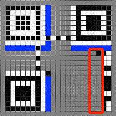
Downward pixel #1 added
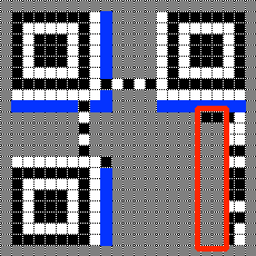
Downward pixel #2 added
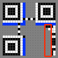
Downward pixel #3 added
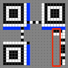
Downward pixel #4 added
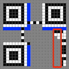
Downward pixel #5 added
Skipping Function Patterns
When a function pattern is encountered, skip any occupied modules until you reach the next unused module.
In the following images, the data bits below the alignment pattern are proceeding in an upward column. Notice that the column overlaps the alignment pattern.


When the alignment pattern is reached, simply skip the modules that are part of the alignment pattern and continue upward.


Then continue adding modules to the column the usual way.


In summary, always proceed normally along the columns, skipping any modules that are used by function patterns or reserved areas. The only exception is the vertical timing pattern, as explained below.
Exception: Vertical Timing Pattern
The vertical timing pattern is the only exception to this rule. When the vertical timing pattern is reached, always start the next column to the left of it. No column should ever overlap the vertical timing pattern.
In the following image, the previous column (upward) is highlighted. The rest of the modules above this column are occupied by function patterns and reserved areas, so the next column must be started, going downard.

As shown in the following images, the next column starts to the left of the vertical timing pattern. The column does not overlap the vertical timing pattern.


Next: Data Masking
After placing the data and error correction bits into the matrix, the QR code specification requires that a mask pattern be applied to the data and error correction bits. The purpose of this step is to reduce the number of hard-to-read patterns in the matrix. Continue to the next section to learn about data masking.